Reinforced Concrete Corroded Columns
Published on Feb 14, 2016
Abstract
Corrosion of steel in concrete is continually growing and causes multibillion dollar problem. This affects the performance and durability of concrete structures world wide. Normally concrete act as a physical barrier to the ingree of aggressive enviournment for the reinforcing steel because of its high alkalinity.
However , corrosion of the reinforcing steel in concrete may result from the use of inappropriate concrete mixes, lack of quality control in mixing , planning and consolidation an entrapping of air in the concrete , resulting in reliability permeable concrete When the structure are exposed to corrosive enviournment, premature failure of R.C columns due to corrosion leads to ultimate structural failure. This research involved the testing of two series (AR 1 and AR 2 ) of RC columns subjected to three levels of corrosion under non-loading condition. Another set of AR 1 and AR 2 specimens were subjected to reinforcement corrosion while maintaining a sustained load.
Corrosion occur in the presence of moisture. For example when iron is exposed to moist air, it reacith oxygen to form reist, Fe2O3, X H2O. Millions of dollars are lost each year because of corrosion . Much of these lose is due to the corrosion . Much of these loss is due to the corrosion of iron and steel, although many other metals is that the oxide formed by oxidation does not firmly adhere to the surface of the metal and flakes off easily causing “pitting”. Extensive pitting eventually causes structural weakness and disintegration of metal.
The involvement of water accounts for the fact that rusting occurs much more rapidly in moist conditions as compared to dry enviournment such as desert. Many other factors affect the rate of corrosion . For example the presence of salt greatly enhances the rusting of metals. This is due to the fact that the dissolved salt increases the conductivity of aqueous solution formed at the surface of the metal and enhances the rate of electro chemical corrosion .
Method of Accelerating reinforcement Corrosion
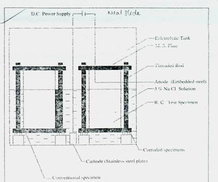
Galvanostatic method was used to accelerate the corrosion of the reinforcement bar, The three different levels of corrosion are studied at 30,60 and 90 days and are designated as first second and third level respectively. Three identical specimens of each series were subjected to three levels of corrosion under non-loading condition As a second phase of the work, another set of AR1, AR2 specimens was subjected to corrosion process under loading condition.
A load of 45 KN was applied to the specimens . The loading was exerted by keeping two 2.5 cm thick steel plates one at the top and the other at the bottom of the specimens and the whole assembly is tightened with threaded road and nuts which was controlled by a torque wrench. Fig.2 given the schematic arrangement of the sustained load corrosion process.
The load decreases as the corrosion proceed with increase in time . To maintain the loads constant throughout the duration of the test, continuous and adjustment of nuts were required . Fig 3 show the specimen after the accelerated corrosion process. Residual Axial Load Test
Axial compression tests were conducted after completion of the accelerated corrosion after completion of the accelerated corrosion process, and the obtained failure load and failure moder are summarized in Table 3.
Axial strain was measured using demountable mechanical strain gauge which is positioned at diametrically opposite side of the specimen. Fig 5 and Fig 6 show the test setup of convetional and corroded column . The failure of conventional columns occurred due to the crackinmg and spalling of the concrete cover. Fig 7 shows the failure pattern of conventional column.
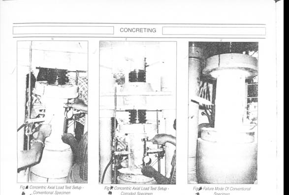
However , it was noticed that the spalling of the concrete cover of the corrosion damaged columns occurred along the height of the columns almost at the same time , showing significant loss of failure load as compared to the conventional column. This is probably because the concrete cover of the corroded column was already delaminated , prior to the failure tests , due to the cracks formed around the spiral reinforcement and cross-sectional loss of steel reinforcement. From Table 3, it can be seen that R2 specimens have higher load carrying capacity than R1 specimens because of increased percentage of area of reinforcement.