Cruise Control Devices
Published on Dec 17, 2015
Abstract
Everyday the media brings us the horrible news on road accidents. Once a report said that the damaged property and other costs may equal 3 % of the world's gross domestic product. The concept of assisting driver in longitudinal vehicle control to avoid collisions has been a major focal point of research at many automobile companies and research organizations.
The idea of driver assistance was started with the 'cruise control devices' first appeared in 1970's in USA. When switched on, this device takes up the task of the task of accelerating or braking to maintain a constant speed. But it could not consider the other vehicles on the road.
An 'Adaptive Cruise Control' (ACC) system developed as the next generation assisted the driver to keep a safe distance from the vehicle in front. This system is now available only in some luxury cars like Mercedes S-class, Jaguar and Volvo trucks the U.S. Department of transportation and Japan's ACAHSR have started developing 'Intelligent Vehicles' that can communicate with each other with the help of a system called 'Co operative Adaptive Cruise Control' .this paper addresses the concept of Adaptive Cruise Control and its improved versions.
ACC works by detecting the distance and speed of the vehicles ahead by using either a Lidar system or a Radar system [1, 2].The time taken by the transmission and reception is the key of the distance measurement while the shift in frequency of the reflected beam by Doppler Effect is measured to know the speed. According to this, the brake and throttle controls are done to keep the vehicle the vehicle in a safe position with respect to the other.
These systems are characterized by a moderately low level of brake and throttle authority. These are predominantly designed for highway applications with rather homogenous traffic behavior. The second generation of ACC is the Stop and Go Cruise Control (SACC) [2] whose objective is to offer the customer longitudinal support on cruise control at lower speeds down to zero velocity [3]. The SACC can help a driver in situations where all lanes are occupied by vehicles or where it is not possible to set a constant speed or in a frequently stopped and congested traffic [2].
There is a clear distinction between ACC and SACC with respect to stationary targets. The ACC philosophy is that it will be operated in well structured roads with an orderly traffic flow with speed of vehicles around 40km/hour [3]. While SACC system should be able to deal with stationary targets because within its area of operation the system will encounter such objects very frequently.
ADAPTIVE CRUISE CONTROL (ACC)
2.1 PRINCIPLE OF ACC
ACC works by detecting the distance and speed of the vehicles ahead by using either a Lidar system or a Radar system [1, 2].The time taken by the transmission and reception is the key of the distance measurement while the shift in frequency of the reflected beam by Doppler Effect is measured to know the speed. According to this, the brake and throttle controls are done to keep the vehicle the vehicle in a safe position with respect to the other. These systems are characterized by a moderately low level of brake and throttle authority.
These are predominantly designed for highway applications with rather homogenous traffic behavior. The second generation of ACC is the Stop and Go Cruise Control (SACC) [2] whose objective is to offer the customer longitudinal support on cruise control at lower speeds down to zero velocity [3]. The SACC can help a driver in situations where all lanes are occupied by vehicles or where it is not possible to set a constant speed or in a frequently stopped and congested traffic [2]. There is a clear distinction between ACC and SACC with respect to stationary targets.
The ACC philosophy is that it will be operated in well structured roads with an orderly traffic flow with speed of vehicles around 40km/hour [3]. While SACC system should be able to deal with stationary targets because within its area of operation the system will encounter such objects very frequently.
2.2 CONSTITUENTS OF AN ACC SYSTEM:
1. A sensor (LIDAR or RADAR) usually kept behind the grill of the vehicle to obtain the information regarding the vehicle ahead. The relevant target data may be velocity, distance, angular position and lateral acceleration.
2. Longitudinal controller which receives the sensor data and process it to generate the commands to the actuators of brakes throttle or gear box using Control Area Network (CAN) of the vehicle.
3. SENSOR OPTIONS:
Currently four means of object detection are technically feasible and applicable in a vehicle environment [2]. They are
1. RADAR
2. LIDAR
3. VISION SENSORS
4. ULTRASONIC SENSOR
The first ACC system used LIDAR sensor.
3.1 LIDAR (Light Detection and Ranging)
The first acc system introduced by Toyota used this method. By measuring the beat frequency difference between a Frequency Modulated Continuous light Wave (FMCW) and its reflection [3].
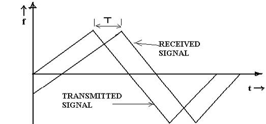
Fig 1.Range estimation using FMCW-LIDAR
A company named Vorad Technologies has developed a system which measured up to one hundred meters. A low powered, high frequency modulated laser diode was used to generate the light signal.
Most of the current acc systems are based on 77GHz RADAR sensors. The RADAR systems have the great advantage that the relative velocity can be measured directly, and the performance is not affected by heavy rain and fog. LIDAR system is of low cost and provides good angular resolution although these weather conditions restrict its use within a 30 to 40 meters range.
3.2 RADAR (Radio Detection and Ranging):
RADAR is an electromagnetic system for the detection and location of reflecting objects like air crafts, ships, space crafts or vehicles. It is operated by radiating energy into space and detecting the echo signal reflected from an object (target) the reflected energy is not only indicative of the presence but on comparison with the transmitted signal, other information of the target can be obtained. The currently used ‘Pulse Doppler RADAR’ uses the principle of ‘Doppler effect’ in determining the velocity of the target [5].
3.2.1 PULSE DOPPLER RADAR:
The block diagram of pulse Doppler radar is as shown in figure.2.
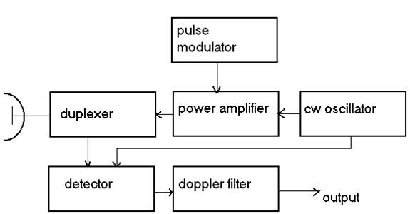
The continuous wave oscillator produces the signal to be transmitted and it is pulse modulated and power amplified. The ‘duplexer’ is a switching device which is fast-acting to switch the single antenna from transmitter to receiver and back. The duplexer is a gas-discharge device called TR-switch. The high power pulse from transmitter causes the device to breakdown and to protect the receiver. On reception, duplexer directs the echo signal to the receiver. The detector demodulates the received signal and the Doppler filter removes the noise and outputs the frequency shift ‘fd’