Advances in Magnetic Field Sensors
Published on Nov 23, 2015
Abstract
The most important milestone in the field of magnetic sensors was when AMR sensors started to replace Hall sensors in many applications where the greater sensitivity of AMRs was an advantage. GMR and SDT sensors finally found applications.
We also review the development of miniaturization of fluxgate sensors and refer briefly to SQUIDs, resonant sensors, GMIs, and magnetomechanical sensors.In recent years, anisotropic magnetoresistive (AMR) sensors with integrated flipping and feedback coils have become standard off-the-shelf devices for use in medium-accuracy applications such as compasses for mobile devices.
After many years of development, giant magnetoresistive (GMR) sensors have finally found applications in angular sensing. Spin-dependent tunneling (SDT) devices are used for applications that require the smallest sensor size. Exciting improvements have been achieved in the sensitivity of resonance magnetometers, but most of the new devices are still in the laboratory phase.
Despite the recent achievements in giant magnetoimpedance (GMI) sensors and orthogonal fluxgates, these devices are still far from the parameters achieved by classical longitudinal fluxgate sensors. The development of magnetic sensor technology has been slow and gradual. Most breaking news about nanosensors with picotesla resolution has turned out to be a bubble. Exaggerated advertisements have resulted in inflated parameters for magnetic devices; we will try to show which factors are critical for real applications of magnetic sensors.
Flux Concentrators
Magnetic flux concentrators (also called flux intensifiers, diverters, or controllers) are made from high permeability, low-power-loss materials. They are routinely used in induction heat treating applications (Fig.1) in a manner similar to that of magnetic cores in power transformers.
There are three traditional functions of flux concentrators in induction hardening:
(a) providing a selective heating of certain areas of the work piece;
(b) improving the electrical efficiency of the induction coil; and (c) acting as an electromagnetic shield to prevent the undesirable heating of adjacent regions. In some cases, magnetic flux concentrators are credited with turning a seemingly impossible development task into a fairly reasonable one.
The basic information about magnetic flux concentrators and concentrator materials, and provides design and selection guidelines for their use in induction heat treating.
Without a concentrator, the magnetic flux would spread around the coil or current carrying conductor and link with the electrically conductive surroundings (auxiliary equipment, metal supports, tools, and fixtures, for example). The concentrator forms a magnetic path to channel the coil’s main magnetic flux in a well-defined area outside the coil.1.
The current distribution in an isolated conductor is shown in Fig. 2(a). The current redistribution within this conductor when it is in close proximity to an electrically conductive work piece is shown in Fig. 2(b). Due to the proximity effect, a significant part of the conductor’s current will flow near the surface that faces the load (the “open surface” of the coil). The balance of the current will be concentrated in the sides of the conductor.
When a magnetic flux concentrator is placed around the work piece, practically all of the current in the coil will be concentrated on the open surface. The concentrator “squeezes” the current to that surface, as shown in Fig. 2(c). This is called a slot effect.1 concentrating the current within the surface of the coil that faces the work piece improves coil-to-work piece magnetic coupling, which results in improved coil electrical efficiency. A reduction in required coil power also can be attributed to the flux concentrator’s ability to localize the magnetic field, as shown in Fig. 2(d). By preventing a major portion of the field from propagating behind it, the concentrator localizes the heated area. As a result, the heated mass of metal will be smaller, which means that less power will be needed to accomplish the required heat treatment.
AMR Sensors
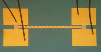
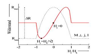
One of the most widely deployed magnetic field sensors is the AMR sensor. AMR stands for anisotropic magnetoresistance. In contrast to GMR sensors („giant magnetoresistance“), which require complex multilayer systems, the AMR sensor is characterized by its simplicity. It consists of a thin permalloy layer and metal stripes (so-called barber poles) which cause a linearization of the sensor characteristics. The spontaneous magnetization lies in the easy axis direction which is fixed by shape anisotropy. A magnetic field along the heavy axis (perpendicularly to the easy axis) provides a rotation of the magnetization in the permalloy strip and thus a change of its resistance.
AMR sensors are nowadays commercially available from various manufacturers, either as primary magnetic field sensors or – in combination with integrated readout electronics – as e.g. rotation speed sensors. In collaboration with different manufacturers we characterize AMR sensors, especially with regard to the noise performance. In addition, we fabricate our own AMR sensors with the goal to tailor magnetometers for various applications where the very low noise of SQUIDs or fluxgate magnetometers is not needed.
Furthermore, we want to investigate the influence of fabrication and geometrical parameters on the sensor noise. The perm alloy films are deposited by rf sputtering, the metal layers for the barber poles and contact pads are deposited either by sputtering of thermal evaporation. Patterning is performed with conventional photolithography in combination with wet-chemistry of Ar plasma etching. In order to characterize the AMR sensors an automated measurement setup was built. A typical sensor characteristic of an AMR sensor without barber poles fabricated without an additional annealing treatment is depicted in the figure below.
Permalloy is the most common material for AMR sensors because it has a relatively large magnetoresistance and because its characteristics are compatible with the fabrication techniques employed to make silicon integrated circuits.
The magnetoresistance of permalloy is less than 4%. As shown in fig-9(a), an integrated sensor normally consists of four perm alloy resistors sputter-deposited on a silicon substrate to form a bridge. An offset voltage in a magnetoresistive bridge can arise from the inherent resistance of the four resistors that are not precisely matched. In designing anisotropic magnetoresistance bridges, one can use a method that greatly reduces the offset from mismatches in the four resistors.
This set/reset method is illustrated in fig-9(b). By changing the direction of the magnetization in the thin film, the bridge output changes sign. Fig-9(b) shows the bridge voltage produced from an applied field when the magnetization is set in one direction and then reversed (reset). This setting of the magnetization is done by applying a strong magnetic field for a short time along the direction desired.
By subtracting the voltage reading when the sensor is in the reset mode from the voltage reading in the set mode, the inherent resistance and its noise (such as temperature effects) is cancelled and the resulting value represents twice the output for the applied field measurement. Typical AMR sensors have a sensitivity range of 103 to 5 × 10⁶ nT with open-loop readout electronics. With closed-loop feedback readout electronic methods, the minimum detectable field can be reduced to better than 0.1 nT for limited bandwidths.
Magnetic Feedback
Another technique for improving the accuracy of any magnetic sensor is feedback compensation of the measured field. Modern AMR sensors have an integrated flat feedback coil, which simplifies the magnetometer design, but may also cause new design problems, as the compensating field is much less homogeneous than that of a solenoid–this may cause linearity error.
The temperature coefficient of sensitivity of a typical AMR sensor may be reduced from 0.25%/K to 0.01%/K by using negative feedback with a sufficient gain; the remaining temperature dependence is due to the temperature coefficient of the field factor of the feedback coil. The temperature coefficient of the offset remains the same (typically 10 nT/K, but varies from piece to piece, even between sensors from the same batch), as feedback has no effect on this parameter. With feedback compensation, the linearity error may be below 300 ppm of the full-scale
The Quantum Mechanics of GMR
To understand how GMR works on the atomic level, consider the following analogies: If a person throws a ball (analogous to a conduction electron) between two sets of rollers turning the same direction (analogous to parallel spin-aligned magnetic layers), the ball tends to go through smoothly. But if the top and bottom rollers turn in opposite directions, the ball tends to bounce and scatter. Alternatively, the GMR effect may be compared to light passing through polarizes. When the polarizers are aligned, light passes through; when their optical axes are rotated with respect to each other, light is blocked.
The resistance of metals depends on the mean free path of their conduction electrons, which, in GMR devices, depends on the spin orientation. In ferromagnetic materials, conduction electrons either spin up when their spin is parallel to the magnetic moment of the ferromagnet, or spin down when they are antiparallel. In nonmagnetic conductors, there are equal numbers of spin-up and spin-down electrons in all energy bands.
Because of the ferromagnetic exchange interaction, there is a difference between the number of spin-up and spin-down electrons in the conduction bands. Quantum mechanics dictates that the probability of an electron being scattered when it passes into a ferromagnetic conductor depends on the direction of its spin. In general, electrons with a spin aligned with the majority of spins in the ferromagnets will travel further without being scattered.
In a GMR spintronic device, the first magnetic layer polarizes the electron spins. The second layer scatters the spins strongly if its moment is not aligned with the polarizer’s moment. If the second layer’s moment is aligned, it allows the spins to pass. The resistance therefore changes depending on whether the moments of the magnetic layers are parallel (low resistance) or antiparallel (high resistance).
Optimal layer thicknesses enhance magnetic-layer antiparallel coupling, which is necessary to keep the sensor in the high-resistance state when no field is applied. When an external field overcomes the antiparallel coupling, the moments in the magnetic layers align and reduce the resistance. If the layers are not the proper thickness, however, the coupling mechanism can destroy the GMR effect by causing ferromagnetic coupling between the magnetic layers.
References
[1] Magnetic Sensors and Magnetometers, P. Ripka, Ed. New York: Artech, 2001.
[2] P. Ripka, “Sensors based on bulk soft magnetic materials: Advances and challenges,” JMMM, vol. 320, pp. 2466–2473, 2008.
[3] R. S. Popovic, Hall Effect Devices. London, U.K.: Institute of Physics, 2004.
[4] P. Leroy, C. Coillot, V. Mosser, A. Roux, and G. Chanteur, “Use of magnetic concentrators to highly improve the sensitivity of Hall effect sensors,” Sensor Lett., vol. 5, pp. 162–166, 2007.